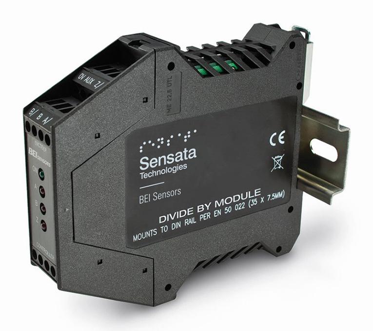
Electronic Modules Divide-By Module EMDR1-DB
Position Sensors & Encoders
The Divide-By Module option provides a method to divide the effective resolution and signal frequency of a quadrature output incremental encoder. The Divide By option is available with the BEI Optical Isolator and Broadcaster. The module receives quadrature counts from an incremental encoder and divides them by a predetermined integer value. The index signal is passed through without modification. When combined with the Optical Isolator a single encoder can be used to feed different control devices, synchronizing their outputs at different ratios. This can lower parts count and reduce overall system costs. This module accepts single ended or differential inputs and divides the signal by a factory set number from 2 to 256. The resulting output signal is a reduced resolution of the input signal. Ideal for use in machine retrofitting and for applications where a different resolution output is needed from the same encoder source. When ordering, make sure to specify the divide-by amount in the model number (see ordering options below).
Industries
Distributors Stock
Part #EMDR1-DB
Need more information?
Contact us to request pricing, availability and customization options
Contact UsDownloads
Specifications
Power:
The divide by module can accommodate standard operating voltages from 5 to 28 VDC. It should never be connected directly to AC power mains. The module draws approximately 75 mA and a green LED indicates the unit is powered. The divide by module does not provide power to the encoder. Any encoders used in conjunction with this module must be connected to their own power.
Signal:
Specifying a divide by module requires knowledge of three system parameters: the DC supply voltage available in the system; the encoder output type (logic levels and driver type); and the input signal specifications of the receiving electronics.
Output Code Format From Encoders
Dual Channel in quadrature plus index and complements. Data lines are designated A, B, Z, A/, B/, Z/ at the module.
Output Signal Type From Encoder
Differential line driver (Use Connection Instructions #1)
Single ended line driver (Use Connection Instructions #2)
Single ended open collector with pull-up resistors internal to encoder
(Use Connection Instructions #3)
Single ended, open collector (Use Connection Instructions #3)
Output Signal Voltage Level From Encoder
5 VDC (TTL, RS422 compatible, line driver)
12-15 VDC
24VDC
Frequency Response of Optical Isolator
1 MHz, maximum
Power Requirements For Optical Isolator
5-28 VDC ±5%, 75mA plus load current
Optical Isolator Output Options
28V/V Line Driver, 100mA source/sink, Vout = Vin
28V/5 Line Driver, 100mA source/sink, Vout = 5V (Derate output current to 50mA with supply voltage > 12VDC)
28V/OC NPN Open Collector, 80mA sink
Protection Level
Supply lines protected against over voltage to 60 volts and reverse voltage
Tristate Outputs
Available as –S Special Feature
Related Products
View All Products