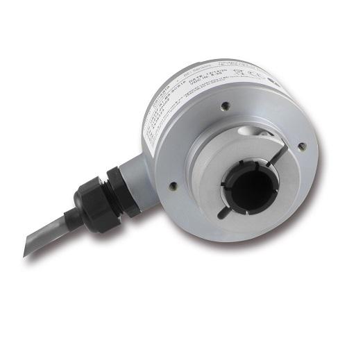
HS25 Series Incremental Encoder 01072-262
Position Sensors & Encoders
The HS25 combines the rugged, heavy-duty features usually associated with shafted encoders into a hollow-shaft style. Its design includes dual bearings and seals for up to IP65 environmental ratings, a rugged metal housing, and a sealed cable gland. This low profile design, just 2” deep, is easily mounted on a through shaft. Securing the encoder to the shaft is simple with a collet-style single screw clamp.
A tether arm and tether block are available options to maintain housing stability during operation.
Applications: Motor feedback – variable frequency drives; paper converting and printing equipment – registration, cut-to-length, cartonizing; robotics – compact size saves space; elevators – traction control
Model: XHS25F-75-R2-SS-1024-ABZC-28V/V-SCS18
Disclaimer: Photos and drawings shown are for illustration purposes only, actual product may vary.
Distributors Stock
Part #01072-262
Need more information?
Contact us to request pricing, availability and customization options
Contact UsFeatures
- Accommodates shafts up to ¾” in diameter.
- Two available tethering styles provides installation flexibility
- Reducer bushings provide both electrical and thermal isolation
- Shaft seal and sealed bearing are standard features to provide IP rating
- Selected configurations available in 1 to 3 days shipment (“Express Encoder” option)
Specifications
| Shaft Bore | 0.750”, 0.625”, 0.500”, 0.375. Diameters 0.625” and under are supplied with insulating sleeves |
| Allowable Misalignment | 0.005: T.I.R. on mating shaft 0.75” from shaft end |
| Bore Runout | 0.001” T.I.R |
| Starting Torque at 25°C | 7 oz-in max. for Through shaft (SS) and 4 oz-in max. for Blind shaft (BS). |
| Bearings | High precision ball bearings, Material: Chrome steel |
| Shaft Material | 6061-T6 aluminum alloy |
| Bearing Housing | Die cast aluminum with protective finish |
| Cover | Die cast aluminum with protective finish |
| Bearing Life | 7.5 X 10⁹ revolutions |
| Maximum RPM | 6,000 RPM (see Frequency Response, below) |
| Moment of Intertia | 17 X 10-4 oz-in-sec2 |
| Weight | 9 oz typical |
| Code | Incremental |
| Output Format | 2 outputs in quadrature, A leads B CCW, 1/2 cycle index , Z, gated with negative B Consult factory for other output formats. |
| Cyles per Shaft Turn | 2 to 80,000 (see table 2) |
| Supply Voltage | 5 to 28 VDC +/- 5% |
| Current Requirements | 100 mA typical +output load, 250 mA (max) |
| Voltage/Output | (See notes) 15/V: Line Driver, 5–15 VDC in, Vout = Vin 28/V: Line Driver, 5–28 VDC in, Vout = Vin 28/5: Line Driver, 5–28 VDC in, Vout = 5 VDC 28/O: Open Collector, 5–28 VDC in, OCout |
| Protection Level | Reverse, overvoltage and line driver output protection diodes |
| Frequency Response | 300 kHz |
| Output Terminations | See Table 1 in the datasheet |
| Enclosure Rating | IP65 Standard with M12 connector or Cable Gland output terminations. (Includes SCS18-M18 option) |
| Temperature | Standard operating temperature -40° C to +85° C; options available at -40° C to +100° C (Consult factory). Storage temperature -40° C to +100° C |
| Shock | 100 g’s for 5 msec duration |
| Vibration | 50 to 2000 Hz @ 30grms |
| Humidity | 98% RH without condensation |
| Type | Family | Housing Configuration | Shaft Bore | Tether | Shaft Seal Configuration | Cycles per Turn | Number of Channels | Complements | Voltage/Output | Output Termination | Hazardous Area Ratings | Special Features |
| X = Express (3 days leadtime) Blank = Standard Leadtime |
HS25 = Hollow Shaft; 2.5” diameter | F = Standard | 75 = 0.750” non-isolated bore 62 = 0.625” isolated bore 62S = 0.625” non-isolated bore 50 = 0.500” isolated bore 37 = 0.375 isolated bore |
Blank = None R1 = Tether Block and Pin R2 = Tether Arm |
SS = Through Shaft Rubber Seals BS = Blind Shaft Rubber Seal |
(Enter Cycles) See Table 2 in the datasheet |
A = Single Channel AB = Dual Quad. Channel ABZ = Dual with Index AZ = Single with Index |
C = Complementary Outputs Blanks = None | 15/V = 5–15 Vin/out 28/V = 5–28Vin/out 28/5 = 5–28Vin/5Vout 28/O = 5–28Vin/OCout |
SM12 = MS3112E12-10P SCSXXX = Shielded, Jacketed Cable with Cable gland seal and cable length in inches, (i.e. SCS18 = 18 inches) SCSXX-M18 = M18 connector (MS3101F18-1P equiv.) on end of XX in. cable. SCS18-M18 is standard option |
Blank = None EX = Intrinsically Safe NI = Non-Incendive Contact factory for voltage options |
S = Special Features specified on purchase orde |

